Designing the Framework of a Parallel Game Engine

1. Introduction
With the advent of multiple cores within a processor the need to create a parallel game engine has become more and more important. It is still possible to focus primarily on just the GPU and have a single threaded game engine, but the advantage of utilizing all the processors on a system, whether CPU or GPU, can give a much greater experience for the user. For example, by utilizing more CPU cores a game could increase the number of rigid body physics object for greater effects on screen, or developing smarter AI that gives it a more human like behavior.
1.1. Overview
The “Parallel Game Engine Framework” or engine is a multi-threaded game engine that is designed to scale to as many processors as are available within a platform. It does this by executing different functional blocks in parallel so that it can utilize all available processors. This is easier said than done as there are many pieces to a game engine that often interact with one another and can cause many threading errors because of that. The engine takes these scenarios into account and has mechanisms for getting proper synchronization of data without having to be bound by synchronization locks. The engine also has a method for executing data synchronization in parallel in order to keep serial execution time at a minimum.
1.2. Assumptions
This paper assumes a good working knowledge of modern computer game development as well as some experience with game engine threading or threading for performance in general.
2. Parallel Execution State
The concept of a parallel execution state in an engine is crucial to an efficient multi-threaded runtime. In order for a game engine to truly run parallel, with as little synchronization overhead as possible, it will need to have each system operate within its own execution state with as little interaction as possible to anything else that is going on in the engine. Data still needs to be shared however, but now instead of each system accessing a common data location to say, get position or orientation data, each system has its own copy. This removes the data dependency that exists between different parts of the engine. Notices of any changes made by a system to shared data are sent to a state manager which then queues up all the changes, called messaging. Once the different systems are done executing, they are notified of the state changes and update their internal data structures, which is also part of messaging. Using this mechanism greatly reduces synchronization overhead, allowing systems to act more independently.
2.1. Execution Modes
Execution state management works best when operations are synchronized to a clock, meaning the different systems execute synchronously. The clock frequency may or may not be equivalent to a frame time and it is not necessary for it to be so. The clock time does not even have to be fixed to a specific frequency but could be tied to frame count, such that one clock step would be equal to how long it takes to complete one frame regardless of length. Depending on how you would like to implement your execution state will determine clock time. Figure 1 illustrates the different systems operating in free step mode of execution, meaning they all don’t have to complete their execution on the same clock. There is also a lock step mode of execution (see Figure 2) where all systems execution and complete in one clock.
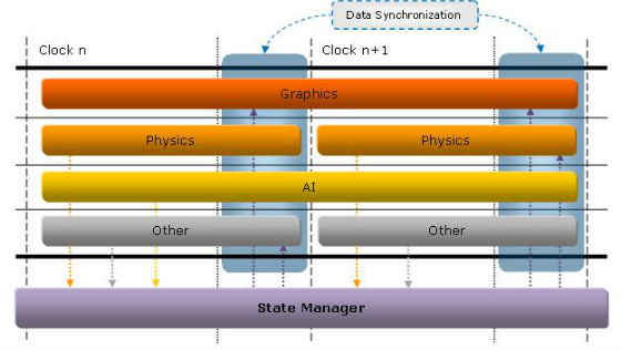
Figure 1: Execution State using Free Step Mode
2.1.1. Free Step Mode
This mode of execution allows systems to operate in the time they need to complete their calculations. Free can be misleading as a system is not free to complete whenever it wants to, but is free to select the number of clocks it will need to execute.
With this method a simple notification of a state change to the state manager is not enough, data will also need to be passed along with the state change notification. This is because a system that has modified shared data may still be executing when a system that wants the data is ready to do an update. This requires more memory and more copies to be used so may not be the most ideal mode for all situations.
2.1.2. Lock Step Mode
This mode requires that all systems complete their execution in a single clock. This is simpler to implement and does not require passing data with the notification because systems that are interested in a change made by another system can simply query the other system for the value (at the end of execution of course).
Lock step can also implement a pseudo free step mode of operation by staggering calculations across multiple steps. One use of this is with an AI that will calculate its initial “large view” goal in the first clock but instead of just repeating the goal calculation for the next clock it can now come up with a more focused goal based on the initial goal.
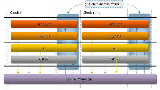
Figure 2: Execution State using Lock Step Mode
2.2. Data Synchronization
It is possible for multiple systems to make changes to the same shared data. Because of this, something needs to be put in place in the messaging to determine which value would be the correct value to use. There are two such mechanisms that can be used:
- Time, where the last system to make the change time-wise has the correct value.
- Priority, where a system with a higher priority will be the one that has the correct value. This can also be combined with the time mechanism to resolve changes from systems of equal priority.
Data values that are determined to be stale, via the two mechanisms, will simply be overwritten or thrown out of the change notification queue.
Because the data is shared, using relative values for data can prove to be difficult as some data may be order dependent when combining it. To alleviate this problem use absolute data values for those that require it so that when systems update their local values they just replace the old with the new. A combination of both absolute and relative data would be the most ideal and would depend on each specific situation. For example, common data, like position and orientation, should be kept absolute as creating a transformation matrix for it would depend on the order they are received, but a custom system that generated particles, via the graphics system, that fully owned the particle information could merely send relative value updates.
3. The Engine
The engine’s design is focused on flexibility, allowing for the simple expansion of its functionality. With that said, it can be easily modified to accommodate platforms that are constrained by certain factors, like memory, etc.
The engine is broken up into two distinct pieces called the framework and the managers. The framework (section 3.1) contains the parts of the game that are duplicated, meaning there will be multiple instances of them. It also contains items that have to do with execution of the main game loop. The managers (section 3.2) are singletons that the game logic is dependent upon.
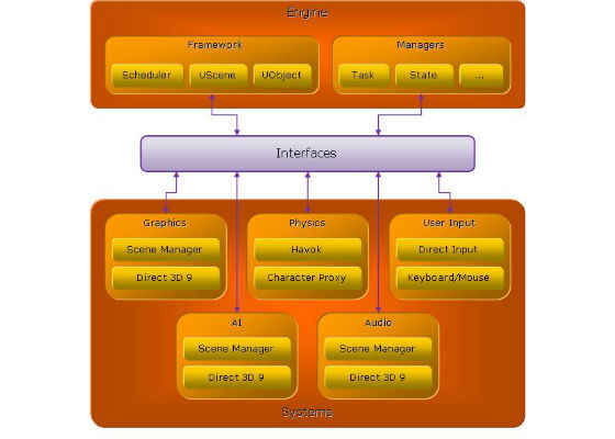
The following diagram illustrates the different sections that make up the engine:
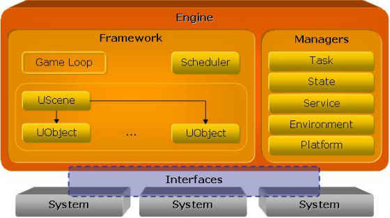
Figure 3: Engine High-Level Architecture
Notice that the game processing functionality, referred to as a system, is treated as a separate entity from the engine. This is for the purpose of modularity, essentially making the engine the “glue” for tying in all the functionality together. Modularity also allows for the systems to loaded or unloaded as needed.
The interfaces are the means of communication between the engine and the systems. Systems implement the interface so that the engine can get access to a system’s functionality, and the engine implements the interface so that the systems can access the managers.
To get a clearer picture of this concept refer to Appendix A, “Example Engine Diagram”.
As described in section 2, “Parallel Execution State”, the systems are inherently discrete. By doing this, systems can run in parallel without interfering with the execution of other systems. This does cause some problems when systems need to communicate with each other as data is not guaranteed to be in a stable state. Two reasons for inter system communication are:
- To inform another system of a change it has made to shared data (e.g. position, or orientation),
- To request for some functionality that is not available within the system (e.g. the AI system asking the geometry/physics system to perform a ray intersection test).
The first communication problem is solved by implementing the state manager described in the previous section. The state manager is discussed in more detail in section 3.2.2, “State Manager”.
To rectify the second problem, a mechanism is included for a system to provide a service that a different system can use. For a more detailed description, you can reference section 3.2.3, “Service Manager”.
3.1. Framework
The framework is responsible for tying in all the different pieces of the engine together. Engine initialization occurs within the framework, with the exception of the managers which are globally instantiated. The information about the scene is also stored in the framework. For the purpose of flexibility the scene is implemented as what is called a universal scene which contains universal objects which are merely containers for tying together the different functional parts of a scene. More information on this is available in section 3.1.2.
The game loop is also located within the framework and has the following flow:
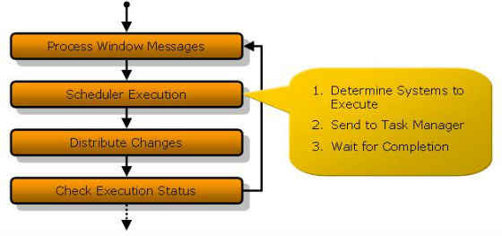
Figure 4: Main Game Loop
The first step in the game loop is to process all pending OS window messages as the engine operates in a windowed environment. The engine would be unresponsive to the OS if this was not done. The next step is for the scheduler to issue the systems’ tasks with the task manager. This is discussed in more detail in section 3.1.1 below. Next, the changes that the state manager (section 3.2.2) has been keeping track of are distributed to all interested parties. Finally, the framework checks the execution status to see if the engine should quit, or perform some other engine execution action like go to the next scene. The engine execution status is located in the environment manager which is discussed in section 3.2.4.
3.1.1. Scheduler
The scheduler holds the master clock for execution which is set at a pre-determined frequency. The clock can also run at an unlimited rate, for things like benchmarking mode, so that there is no waiting for the clock time to expire before proceeding.
The scheduler submits systems for execution, via the task manager, on a clock tick. For free step mode (section 2.1.1), the scheduler communicates with the systems to determine how many clock ticks they will need to complete their execution and from there determines which systems are ready for execution and which systems will be done by a certain clock tick. This amount can be adjusted by the scheduler if it determines that a system needs more execution time. Lock step mode (section 2.1.2) has all systems start and end on the same clock, so the scheduler will wait for all systems to complete execution.
3.1.2. Universal Scene & Objects
The universal scene and objects are containers for the functionality that is implemented within the systems. By themselves, the universal scene and objects do not possess any functionality other than the ability to interact with the engine. They can, however, be extended to include the functionality that is available in a system. This gives them the ability to take on the properties of any available system without having to be tied to a specific system giving it loose coupling. Loose coupling is important as it allows the systems to be independent of each other giving them the ability to run in parallel.
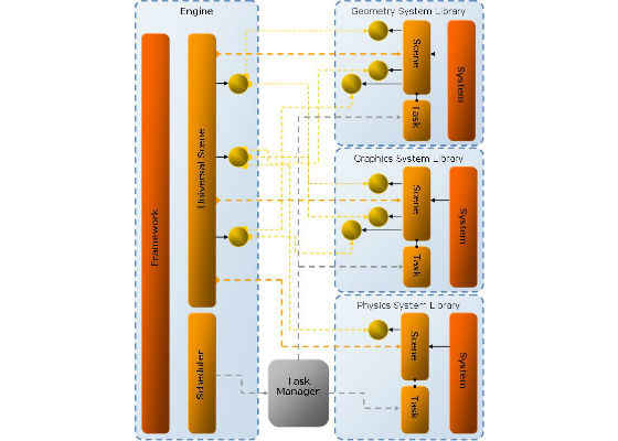
The following diagram illustrates the universal scene and object extension of a system:
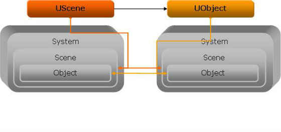
Figure 5: Universal Scene and Object Extension
An example of how extensions work is as follows: A universal scene is extended to have graphics, physics, and other properties. The graphics scene extension would be responsible for initializing the display and other things, and the physics scene extension would be responsible for setting up the rigid body world, like gravity, etc. Scenes contain objects, so a universal scene would have several universal objects. A universal scene can also be extended to have graphics, physics, and other properties. The graphics object extension would be responsible for drawing the object on screen, and the physics object extension would be responsible for the rigid body interaction of the object with other rigid bodies.
For a more detailed diagram on the relationship of the engine with the systems see Appendix B, “Engine and System Relationship Diagram”.
Another thing to point out is that the universal scene and universal object are responsible for registering all their extensions with the state manager so that the extensions will get notified of changes made by other extensions (i.e. other systems). An example would be the graphics extension being registered to receive notification of position and orientation changes made by the physics extension.
More information about the system’s components can be found in section 5.2, “System Components”.
3.2. The Managers
The managers provide global functionality within the engine and are implemented as singletons, meaning there will only be one instantiation made available for each type of manager. The reason they are singletons is because their resources should not be duplicated as they will cause redundancy and potential processing performance implications. They also provide common functionality that will be useable across all the systems.
3.2.1. Task Manager
The task manager handles scheduling of a system’s task within its thread pool. The thread pool creates one thread per processor to get the best possible n-way scaling to processors and prevents over subscription avoiding unnecessary task switching within the OS.
The task manager receives its list of tasks to execute from the scheduler as well as which tasks to wait for execution to complete. The scheduler gets its list of tasks to execute from the different systems themselves. There will only be one primary task per system, this is commonly known as functional decomposition, but each primary task is allowed to issue as many sub-tasks as it wants to for operating on its data, which is called data decomposition.
The following demonstrates how the task manager could issue tasks onto threads for execution on a quad core system:
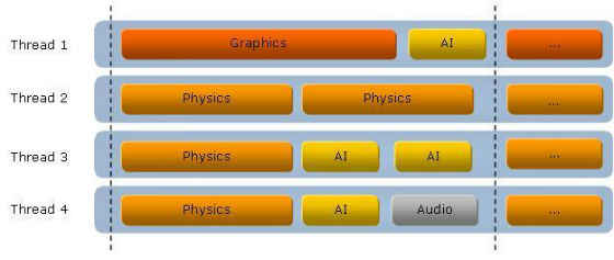
Figure 6: Task Manager Thread Pool Example
Aside from access by the scheduler for issuing of primary tasks, the task manager also has an initialization mode where it will call systems serially from each thread so that the systems can initialize any thread local storage they require for execution.
For some help getting started on implementing a task manager, refer to Appendix D, “Tips on Implementing Tasks”.
3.2.2. State Manager
State management is part of the messaging mechanism that tracks and distributes change notifications made by a system to other interested systems. To reduce unnecessary change notification broadcasts, systems must register with the state manager for changes they are interested in receiving. This mechanism is based on the observer design pattern which is described in more detail in Appendix C, “The Observer Design Pattern”. In a nutshell, the observer design pattern has the basic premise of an observer observing a subject for any changes, with a change controller acts as a mediator between the two.
This mechanism works as such: 1) The observer registers the subject it wants to observe with the change controller (or state manager), 2) when the subject has changed one of its properties it sends a change notification to the change controller, 3) the change controller, when told to by the framework, will distribute the change notifications of the subject to the observer, and 4) the observer will query the subject for the actual changed data.
Free step mode of operation (section 2.1.1) introduces some extra complexities to this mechanism. Firstly, it will be necessary to include the data along with the change notification as a system that has modified shared data may still be executing and therefore cannot be queried for its value. Next, if a system is not yet ready to receive the changes at the end of a clock tick, the state manager will need to hold on to that data until all systems registered for it are finally ready to receive it.
The framework implements two state managers, one for handling changes on the scene level and another for handling changes on the object level. The reason for this is that scenes and objects, for the most part, have different messages that are relevant to them so separating them removes the need to process unnecessary messages. However, any object changes that are relevant to the scene will be registered with the scene so that it will receive those change notifications.
In order to remove any synchronization overhead, the state manager will have a change queue for each thread created by the task manager. This way there is no synchronization required when accessing the queue. The queues can then be merged after execution using the method described in section 2.2.

Figure 7: Internal UObject Change Notification
While you would think that change notifications would have to be distributed serially, it is possible to parallelize this action. When systems are executing their tasks they operate across all their objects. For example, the physics system would be moving around objects, checking for collisions, and setting new forces, etc. as physics object interact with each other. During change notification a system’s object is no longer interacting with other objects from its own system but is now interacting with other extensions in the universal object it is associated with. This means that universal objects are now independent of each other so each universal object can be updated in parallel. Take note, though, that there may be some corner cases that need to be accounted for with synchronization. Still, something that looked hopelessly serial can now get some parallelization.
3.2.3. Service Manager
The service manager provides access to functionality to systems that otherwise would not have such functionality. A thing to note is that the service manager does not provide this directly but has the interfaces defined for it and any systems that implement the exposed interface functionality will register themselves with the service manager.
There is only a small set of services available as the design of the engine is to keep systems running as discretely as possible. Also, systems are not free to provide any service they so choose but only those provided for by the service manager.

Figure 8: Service Manager Example
The service manager has another role of providing access to the properties of the different systems to each other. Properties are values of each system that are specific to a system and are therefore not passed in the messaging system. Some examples of these are the screen resolution of the graphics system, or the gravity value of the physics system. The service manager gives access to all these properties to the different systems without giving them direct control over them. It also makes it so that the property changes are queued up and are only issued during serial execution. Take note that accessing another system’s properties is a rare occurrence and should not be used as common practice. This is made available for things like the console window, for example, to turn on/off wireframe mode in the graphics system, or for the user interface system to change the screen resolution as requested by the user. They are essentially used for things that will not change from frame to frame.
3.2.4. Environment Manager
The environment manager provides the functionality for the engine’s running environment. The following is a list of the function groups provided by the environment manager:
- Variables – variable names and data that are shared across the entire engine. The variables are usually set upon loading a scene or some user settings, and are queried in the engine and or by the different systems.
- Execution – information about the execution, such as the end of a scene or end of the program. This can be set or queried for by either the engine or the systems.
3.2.5. Platform Manager
The platform manager handles all abstraction of OS calls and also provides added functionality beyond just a simple abstraction. This gives the benefit of encapsulating several common functional steps within one call instead of all the callers having to implement them or know about the nuances of the OS calls.
An example of this is the call in the platform manager to load a system’s dynamic library. Aside from loading a system in, it also gets the function entry points and then calls the library’s initialization function. It will also keep around a handle to the library and then unloads it upon exit of the engine.
The platform manager is also responsible for providing information about the processor, such as which SIMD instructions are supported and some others, and initializing some of the behavior for the process. This is a query only functionality that systems can use.
4. Interfaces
The interfaces are the means of communication between the framework, the managers, and the systems. The framework and the managers reside within the engine and therefore the framework has direct access to the managers. The systems, however, reside outside of the engine and have different functionality from each other making it necessary to have a common method for accessing them. Also, the systems do not have direct access to the managers so they also need a method for accessing the managers but not necessarily the full functionality as certain items should only be accessible to the framework.
The interfaces provide a set functionality that needs to be implemented in order to have a common method of access. This makes it unnecessary for the framework to know the details about a specific system as it can communicate to it through a known set of calls.
4.1. Subject and Observer Interfaces
The subject and observer interfaces are used for the registration of the observer with the subject and for passing of change notifications from the subject to the observer. A default subject implementation is also provided as the functionality to handle observer registration/de-registration is common to all subjects.
4.2. Manager Interfaces
The managers, even though they are singletons, are only directly available to the framework which means that the different systems do not have access to them. In order to provide access, each manager would have an interface that exposes a subset of its functionality. The interface would then be passed to the system when it gets initialized and the systems would then have access to a subset of the manager.
The interface defined is dependent upon the manager and therefore is not a common interface but specific to that manager.
4.3. System Interfaces
The systems need to implement interfaces in order for the framework to get access to its components. Without it the framework would have to implement a specific implementation of each new system that gets added to the engine.
There are four components to a system so there are four interfaces a system must implement. They are: System, Scene, Object, and Task. These different components are covered in section 5, “Systems”. The interfaces are the means of getting these components. The System interface provides methods for creating and destroying scenes. Scene interfaces provide methods for creating and destroying objects and a method for retrieving the primary task. The Task interface is used by the task manager when issuing tasks within its thread pool.
The scene and object interfaces also derive from the subject and observer interfaces as these are the pieces of the system that need to communicate with one another, and with the universal scene and object they are attached to.
4.4. Change Interfaces
There are also some special interfaces that are used for passing data between the systems. Any systems that make these specific modifications must also implement the interface. An example of this kind of interface is geometry. The geometry interface would have methods for retrieving the position, orientation, and scale for a certain item. Any systems that make modifications to geometry would need to implement this interface so that a different system would be able to access the geometry changes without needing to know about the other system.
5. Systems
The systems are what provide the game functionality to the engine. Without them the engine would just spin endlessly without any tasks to perform. In order to keep the engine from having to know about all the different system types, systems must implement the interfaces described in section 4.3, “System Interfaces”. This makes it much simpler to add a new system to the engine since the engine won’t need to know about the details.
5.1. Types
The engine should have some predefined systems types that go along with them for standard game components. Some examples are as follows: Geometry, Graphics, Physics (rigid body collision), Audio, Input, AI, and Animation.
A custom type is also recommended for systems that implement functionality outside of the common functional blocks in a game. Take note that any systems that modify the custom type’s specific data items will need to know about the custom type’s interface as the engine does not provide this information.
5.2. System Components
A system has several components to it that need to be implemented. They are as follows: System, Scene, Object, and Task. These components are all used to communicate with the different sections within the engine.
The following diagram demonstrates the relationship between the components:
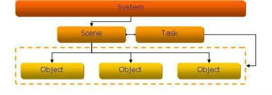
Figure 9: System Components
For a more detailed diagram on the relationship of the systems with the engine, refer to Appendix A, “Engine and System Relationship Diagram”.
5.2.1. System
The system component, or system, is responsible for initializing system resources that will remain more or less constant throughout the execution of the engine. An example of this is the graphics system analyzing all the passed in resource locations to determine where they are located for quicker loading upon use of the resource. The screen resolution would also be another item set by the graphics system.
The system is also the main entry point for the framework and provides information about itself, such as its type, and provides methods for creation and destruction of scenes.
5.2.2. Scene
The scene component, otherwise known as a system scene, is responsible for handling resources that are pertinent to the existing scene. The universal scene uses this scene as an extension of its functionality to make available the properties this system scene provides. An example of this component is the physics scene creating a new world and setting the gravity for the world upon scene initialization.
The scene also provides methods for creation and destruction of objects. It also owns the task component, which is used to operate on the scene, and provide a method for retrieving it.
5.2.3. Object
The object component, alternatively a. system object, is an object within the scene and is typically associated with what is visible to the user on screen. The universal object uses this object component as an extension of its functionality to allow the properties this object provides to be exposed via the universal object.
An example of how this could be used is a universal object extending geometry, graphics, and physics to create a beam of wood on screen. The geometry would hold the position, orientation, and scale information of the object, the graphics system would display it on screen using the given mesh, and the physics system would apply rigid body collision to it so that it would interact with other rigid body objects and gravity.
In certain situations a system object may be interested in the changes of a different universal object, or one of its extensions. In this case a link can be established so that the system object can observe the other object.
5.2.4. Task
The task component, referred to as a system task, is responsible for operating on the scene. When the task receives a command to update, from the task manager, it will perform the system’s functionality on the objects within the scene.
The task can also choose to subdivide its execution into subtasks and schedule the subtasks with the task manager for even more threaded execution. Doing this allows the engine to scale more readily to a configuration with multiple processors. This technique is known as data decomposition.
During the task’s update of the scene is when any modifications done to its objects are posted to the state manager. Refer to section 3.2.2 for more information about the state manager.
6. Tying It All Together
This is a lot of information to absorb all at once, and the different sections aren’t really separate from one another. The entire engine execution can be broken up into several stages as described in the following sections.
6.1. Initialization Stage
Engine execution begins by initializing the managers and the framework.
- The framework calls the scene loader to load in the scene.
- The loader determines what systems the scene is using then calls the platform manager to load those modules.
- The platform manager loads the modules, passes in the manager interfaces, then calls into them to create a new system.
- The module returns a pointer to the instantiated system which implements the system interface.
- The system module will also register any services it provides with the service manager.

Figure 10: Engine Manager and System Initialization
6.2. Scene Loading Stage
Control returns to the loader which loads the scene.
- The loader creates a universal scene and calls each system interface to instantiate system scenes, extending the functionality of the universal scene.
- The universal scene checks each system scene for what shared data changes they could possibly make and what shared data changes they would like to receive.
- The universal scene then registers the matching system scenes with the state manager so that they will be notified of the changes.
- The loader creates a universal object for each object in the scene and determines which systems will be extending the universal object. The universal object follows a similar system object registration pattern with the state manager as that of the universal scene.
- The loader instantiates system objects via the system scene interfaces it previously received and extends the universal objects with the system objects.
- The scheduler then queries the system scene interfaces for their primary tasks because the scheduler is responsible for issuing the primary tasks to the task manager during execution.
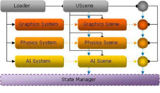
Figure 11: Universal Scene and Object Initialization
6.3. Game Loop Stage
- The platform manager is called to process all window messages and/or other platform specific items that are needed for operation on the current platform.
- Execution is then transferred to the scheduler, which waits for the clock time to expire before proceeding.
- The scheduler, for free step mode, checks which of the system tasks completed execution in the previous clock. All tasks that are done (i.e. ready to execute) get issued to the task manager.
- The scheduler will now determine which tasks will complete on the current clock and waits for completion of those tasks.
- For lock step mode, the scheduler issues all tasks and waits for them to complete for each clock step.
6.3.1. Task Execution
Execution is transferred to the task manager.
- The task manager queues up all tasks submitted to it and starts processing each task as threads become available. (Task processing is specific to each system. Systems can operate using only one task or they can issue more tasks which get queued in the task manager, thus potentially getting executed in parallel).
- As tasks execute they will operate on the entire scene or on specific objects and modify their internal data structures.
- Any data that is considered as shared, like position and orientation, needs to get propagated to the other systems. The system task does this by having the system scene or system object (whichever was changed) inform their observer of the change. In this case the observer is actually the change controller located in the state manager.
- The change controller queues up the change information to be processed later, but change types that the observer is not interested in are simply ignored.
- If the task needs any services it goes through the service manager to call into the provided service. The service manager can also be used to change the property of a different system that isn’t exposed via the messaging mechanism (e.g. the user input system changes the screen resolution of the graphics system).
- Tasks can also call into the environment manager to read environment variables, change the runtime state (e.g. pause execution, go to next scene, etc.).
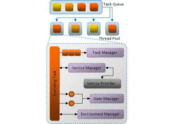
Figure 12: Task Manager and Tasks
6.3.2. Distribution
Once all tasks targeted for the current clock have completed execution, the main loop calls the state manager to distribute the changes.
- The state manager calls each of its change controllers to distribute the changes they have queued up. This is done by going through each subject’s changes and seeing which observer was listening to that subject.
- The change controller then calls the observer informing it of the change (a pointer to the subject’s interface is also passed to the observer). For free step mode, the observer gets the changed data from the change controller, but for lock step mode the observer queries the subject for the data.
- The observers that are interested in the changes done by a system object will typically be other system objects that are all attached to the same universal object. This makes it possible for the change distribution to be broken up into tasks for execution in parallel. To limit synchronization, group together in a task any universal objects’ extensions that are linked.
6.3.3. Runtime Check and Exit
The final step of the main loop is to check the runtime’s state. There are several runtime states like: run, pause, next scene, etc. If the runtime state is set to run it will repeat the entire game loop. If the runtime is set to exit then it exits the game loop, frees up resources, and exits the application. Other runtime states can be implemented like pause, go to next scene, etc.
7. Final Thoughts
The key takeaway from all of this is section 2, “Parallel Execution State”. Designing systems for functional decomposition, coupled with data decomposition will deliver a good amount of parallelization and will also ensure scalability with future processors with an even larger amount of cores. Remember to use the state manager along with the messaging mechanism to keep all data in sync with only minimal synchronization overhead.
The observer design pattern is a function of the messaging mechanism and some time should be spent learning it so that the most efficient design possible can be implemented to address the needs of your engine. After all, it is the mechanism of communication between the different systems to synchronize all shared data.
Tasking plays an important role in proper load balancing. Following the tips in Appendix D will help you create an efficient task manager for your engine.
As you can see, designing a highly parallel engine is manageable by using clearly defined messaging and structure. Properly building parallelism into your game engine will give it significant performance gains on modern and all future processors.
8. About the Author
Jeff Andrews is an Application Engineer with Intel working on optimizing code for software developers, currently focused on PC gaming. He also researches different technologies for enhancing performance or for adding new features to games, which included a role of lead architect for Intel’s Smoke demo framework.
Appendix A. Example Engine Diagram
The main game loop begins processing (see Figure 4, “Main Game Loop” for a graphical representation of this).
Appendix B. Engine and System Relationship Diagram
Appendix C. The Observer Design Pattern
The observer design pattern is documented in the book “Design Patterns: Elements of Reusable Object-Oriented Software,” written by Erich Gamma et al., and originally published by Addison-Wesley in 1995.
The basic premise of this pattern is that any items interested in data or state changes in other items are not burdened with having to poll the items from time to time to see if there are any changes. The pattern defines a subject and an observer that are used for the change notification. It works by having an observer observe a subject for any changes. The change controller acts as a mediator between the two. The following diagram illustrates the relationship:
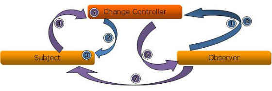
Figure 13: Observer Design Pattern
The following is the flow of events:
1. The observer registers itself with the subject that it wants to observe changes for via the change controller.
2. The change controller is actually an observer. Instead of registering the observer with the subject it registers itself with the subject and keeps its own list of which observers are registered with which subject.
3. The subject inserts the observer (actually the change controller) in its list of observers that are interested in it; optionally there can also be a change type which identifies what type of changes the observer is interested in – this helps speed up the change notification distribution process.
4. When the subject makes a change to its data or state it notifies the observer via a callback mechanism and passes information of the types that were changed.
5. The change controller queues up the change notifications and waits for the signal to distribute them.
6. During distribution the change controller calls the actual observers.
7. The observers query the subject for the changed data or state (or get the data from the message).
8. When the observer is no longer interested in the subject or is being destroyed, it deregisters itself from the subject via the change controller.
Appendix D. Tips on Implementing Tasks
While task distribution can be implemented in many different ways, it is best to keep the number of worker threads equal to the number of available logical processors of the platform. Avoid setting the affinity of tasks to a specific thread as the tasks from the different systems will not complete at the same time and can lead to a load imbalance among the worker threads, effectively reducing your parallelization. It will also be worth your while to investigate using a tasking library, like Intel’s Threading Building Blocks for example, which can simplify this process.
There are some optimizations that can be done in the task manager to ensure CPU friendly execution of the different task submitted. They are as follows:
- Reverse Issuing, if the order of primary tasks being issued is fairly static, the tasks can then be alternately issued in reverse order from frame to frame. The last task to execute in a previous frame will more than likely still have its data in the cache, so by issuing the tasks in reverse order for the next frame it will all but guarantee that the CPU caches will not have to be repopulated with the correct data.
- Cache Sharing, some multi-core processors have their shared cache split into sections so that two processors may share a cache, while another two share a separate cache. By issuing sub-tasks from the same system onto processors sharing a cache it will increase the likelihood that the data will already be in the shared cache.
For more such intel resources and tools from Intel on Game, please visit the Intel® Game Developer Zone
Source: https://software.intel.com/en-us/articles/designing-the-framework-of-a-parallel-game-engine