Getting started with Arduino and sensors
You’ve obviously heard of the Arduino boards and how they’ve revolutionised hobby electronics. Here’s a little primer to get you started.

You’ve heard a lot about ‘Internet of Things’ and probably bought yourself an Arduino kit along with a few more sensors but you can’t figure out how to exactly use them! If that sounds like you, then you’re at the right place. Before we begin, I’ll recommend you to skim through the “Fast Track to Arduino for Everyone” and of course, if you want to see a preview of what you can expect to build after reading this article, check out DIY article about Home Automation. And of course, I’m assuming that you know basic programming stuff, knowing how ‘if’ statements work & what libraries are, is the bare minimum for this article.
Here’s what you’ll need:
- An Arduino Uno (Obviously!)
- Jumper wires (Make it yourself!)
- Breadboard (Optional, but helpful)
- Arduino IDE (Get it here)
There are undoubtedly a lot of sensors available and covering all of them won’t be feasible and that’s why I’ll cover the most frequently used sensors. So let’s get started!
Ultrasonic Distance Sensor
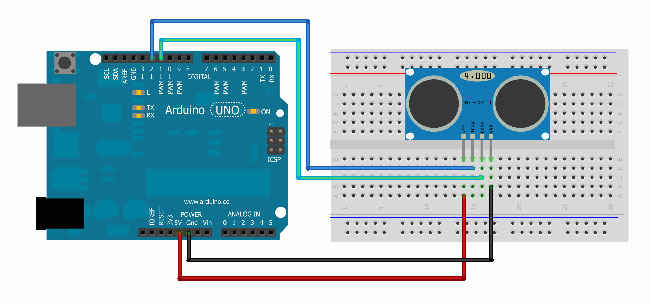
You would have probably read about the SONAR that’s used in ships. By taking the same concept into a small form factor we get a distance sensor. This sensor is available in multiple variants and I’ll be using the ‘HC-SR05’ variant. It can easily detect range between 2 to 450 cm and has 5 different pins, out of which, we don’t need the ‘OUT’ pin for now. To brief you a little, the ‘trigger’ pin will send the pulse and the ‘ECHO’ pin would wait for it to return. The other two pins, GND & VCC, are common and found on almost every component, ‘GND’ pin stands for ‘ground’ and the ‘VCC’ pin means ‘5v input’. The connection is fairly simple; you need to connect the sensor to the Arduino directly (you may also use a breadboard). Using the jumper wires, connect the ‘GND’ pin to the ‘GND’ port of the Arduino and connect the ‘VCC’ pin to the ‘5v’ port on your Arduino. The ‘TRIG’ and ‘ECHO’ pin can be connected to any of the Arduino’s Digital pins. For now, I’m connecting ‘TRIG’ to Digital pin no. 12 and the ‘ECHO’ to pin no. 11. And don’t forget to connect the Arduino to your computer using the USB cable.
The beauty of these sensors is that most of them have a library function available, which basically ease our work since we don’t need to re-invent the wheel. The library for this sensor is named as “NewPing” and you can get it from here and then unzip it into the Documents –> Arduino –> libraries folder. Open up the Arduino IDE (or restart in case it was already open) and on the menu bar, navigate to FileSketchbooklibrariesNewPingNewPingExample. Clicking on it would open up another Arduino window that has got all the code necessary to use the Distance Sensor. Click on the Upload button and a few LEDs would blink on the Arduino. After 2-3 seconds open up the “Serial Monitor” under ‘Tools’ menu option and there you go! You’d be seeing the distance between the sensor and the object in front of it. Using a flat surfaced object will get you better results.
You don’t happen to write any code this time since most of it is handled by the library. However, if you’ve noticed then the distance is actually returned by the function named ‘sonar.ping_cm()’. So, yeah, go on, assign that to a variable and use the variable for your programs. You can make a car that turns automatically if something comes within ‘x’ units or maybe, automate the lights in your home, so that if something comes within ‘x’ units then turn on or off the lights.
PIR Motion Sensor
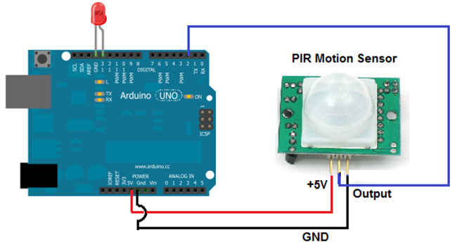
Talk about detecting motion and here we have our Rs.100 sensor that will detect motion for you. As the name suggests, PIR stands for Passive Infrared and it works by detecting differences in Infrared light emitted by objects. As soon as it notices any differences in infrared levels, it registers it as motion. It comes with three pins VCC (5 volts), GND and OUT.
The connection is again pretty simple. Connect the VCC pin to the ‘5 Volt’ port on the Arduino and the ‘GND’ pin goes into the GND port. In fact, these are some conventions that you must get used to by now because you’ll encounter these two pins in almost every sensor. And the other pins are generally connected to the Digital pins and in the PIR sensor, connect the ‘OUT’ pin to the Digital Pin no. 8 (you can choose other ports too, it’s totally your choice, just make sure to make relevant changes in the code). Open up the Arduino IDE and enter the code as given on here. This code will turn ON or OFF the onboard LED light if any motion is detected. So, edit that as per your program’s requirement and you’ll start using the sensor.
Temperature and Humidity Sensor
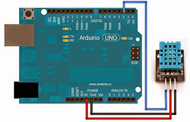
Almost every variant must have at least three pins, each for 5 volts, ground and signal respectively. They work by calculating the electrical resistance between the two electrodes that is present beneath it but you need not worry about that, rather, let’s get familiar with its connections. Chances are that instead of ‘VCC’ or ‘GND’, you may notice that it has plus and minus signs marked respectively. ‘SIGNAL’ pin would be marked with an ‘S’. This time, try to connect them with Arduino on your own (after all, you won’t blow it up). For now, we’ll connect the SIGNAL pin to the DIGITAL pin no. 7.
Fortunately, we’ve got a library function for this sensor which you can download from here and extract it into the Documents –> Arduino –> libraries folder. Get back to Arduino IDE and get the sample code from here. Hit the upload button and open up the serial monitor and you’ll see the temperature and the humidity coming up.
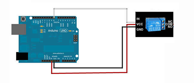
Relay
This exactly isn’t a sensor but is useful as it acts as an electric switch and you would be using it often. It generally comes in multiple channels which translate into “how many individual switches you want?” Buying a ‘5 Volt 4 Channel relay’ would be ideal for most of you. It will have 4 pins, 1 for each switch and 2 more pins for GND and 5 volts. On the other side, the relay’s switch will contain 3 ports. C stands for Common, NO stands for Normally Open and NC means Normally closed. One end of the wire will go in the ‘Common’ port and the other in either of the remaining two ports, NC or NO, depending on your usage.
Library file for this one would make no sense since all it needs to do is to accept either HIGH (1) or LOW (0) commands from Arduino. I’ve made a small program that will demonstrate the usage of relay using the temperature sensor. You can copy the code from here and as you can see, I’ve used the functions from Temperature sensor, thus, if the temperature is above 20 it will turn ON the appliance (if it doesn’t then you’ll need to put the ‘second’ wire into NO port).
And guess what, you just used two different sensors to build a project that is intuitive enough to take surrounding’s temperature and ‘react’ accordingly. Likewise, there are other tons of available sensors which you can combine together and create something more awesome. Check out other Open source hardware and other projects too! Happy DIY!
Disclaimer: The views expressed in this section are of the respective Digit Squad members. Neither Digit nor 9.9 Media takes responsibility of their claims whatsoever.
This article was first published in the March 2016 issue of Digit magazine. To read Digit's articles first, subscribe here or download the Digit e-magazine app.