Optimizing the Rendering Pipeline of Animated Models Using the Intel Streaming SIMD Extensions

Introduction
The following articles describe the individual routines used in the rendering pipeline and how they are optimized using the Intel Streaming SIMD Extensions.
Most of today's computer games render animated polygonal models with real-time lighting and shadows. The computer games DOOM* III (August 2004) and Quake* 4 (October 2005) are no exception. Both computer games use a skeletal animation system. A polygonal mesh often referred to as a 'skin' continuously changes shape with an underlying structure often referred to as a 'skeleton'. By animating the skeleton the skin is transformed. The process of transforming the skin is referred to as 'skinning'. Both games also use shadow volumes to define the regions in space that are in shadow of occluders. A shadow volume is defined by a polygonal boundary representation of the volume containing the shadow of a polygonal occluder.
The articles below provide an overview of the SIMD optimized rendering pipeline of animated models which is equivalent, but superior in performance to the one used in the computer game DOOM III. This improved rendering pipeline is implemented in the computer game Quake 4. Most of the rendering pipeline runs on the CPU while several of the steps in the pipeline could run on a GPU as available on many of today's graphics cards.
However, running most of the pipeline on the CPU improves compatibility across a wide range of systems. Older systems may have graphics cards (like the GeForce2 and GeForce4MX) that do not support the necessary features to perform animation and skinning on the GPU. Graphics cards that do allow skinning on the GPU may have limitations that force large skeletal models to be subdivided into multiple meshes which reduces efficiency. Furthermore the post-transformed skin is needed to construct shadow volumes and current graphics cards do not allow this data to be retrieved after it has been processed. Shadow volume construction can be offloaded completely to the GPU but this may not improve performance if the occluders have high triangle counts or if there are a lot of shadow casting light sources. For these reasons the computer games DOOM III and Quake 4 run most of the pipeline on the CPU allowing the games to run on a wide range of system configurations. Furthermore, the pipeline running on the CPU has virtually no limitations and the SIMD optimizations make the pipeline competitive with (partial) GPU implementations.
The rendering pipeline can be subdivided into four general stages. These stages are animation, skinning, shadow volume construction and clipping & rasterization. The figure below shows these stages as large light gray blocks. Each stage is subdivided into smaller steps where the processed data is shown in slanted boxes and the routines that process this data are shown in darker gray boxes. The numbers in the black corners of these boxes correspond to the articles at the bottom that describe the routines and how they are optimized using the Intel Streaming SIMD Extensions. The blue balloons show how many times faster the SIMD optimized routines are relative to reference implementations in C/C++ when comparing the hot cache clock cycle counts on an Intel® Pentium® 4 Processor on 90nm Technology.
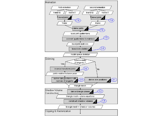
The animation system can blend one or more animations. In the figure above only two animations are shown but many more animations can be blended together to create a complex mixture of motion. An animation is a sequence of animation frames. Each animation frame defines a pose of the skeleton as a list of joint positions and orientations where the orientations are described with quaternions. The position and orientation of a joint are relative to the parent of the joint in the hierarchy of the skeleton.

Click image for a larger view.
The system takes two frames for time t0 and t1 from an animation such that the current time is inbetween t0 and t1. The system then interpolates between these two frames to get a pose of the skeleton for the current time. The interpolated frames from all animations that are being played are then blended together to get the final pose of the skeleton. Next the joint positions and quaternions are transformed into 3×4 matrices. Furthermore the joint matrices are transformed with the joint matrices of their parents to create a skeleton in model space.

Click image for a larger view.
The skeleton in model space is used to animate a triangle mesh often referred to as skinning. Based on whether the triangle mesh is used for rendering or only to create shadow volumes or for collision detection the system can decide upon the best approach to skinning. If the model is not rendered with diffuse, specular and normal maps there is usually no need to calculate normal and tangent vectors at vertex positions. Time can be saved by not animating and calculating these additional vertex properties if they are not needed. The approach to skinning that does calculate normal and tangent vectors requires the joints of the skeleton to be transformed such that they are relative to the joints of a base pose which is transformed to create the animated mesh.

Click image for a larger view.
In the next stage shadow volumes are constructed for every light source interacting with the triangle mesh. A shadow volume defines the regions in space that are in shadow of an occluder in object space with additional geometry. Shadow volumes can be constructed for point lights, spot lights and directional light sources and always produce pixel-accurate but hard shadows. Before any shadow volumes can be constructed the plane equations of the triangles in the triangle mesh need to be derived. These plane equations are used to find the triangles that face towards or away from a light source and to determine the shadow silhouette edges of the geometry. Such silhouette edges are the boundaries between lit and unlit triangles.

Click image for a larger view.
In the last stage, which typically runs on the GPU, the triangle meshes and shadow volumes are clipped and rasterized. The shadow volumes are rendered to the stencil buffer which is queried when the triangle meshes are rendered on screen to determine which pixels are in shadow. To determine the regions in space that are in shadow of a triangle mesh the stencil buffer is first cleared to all zeros. The shadow volume for the triangle mesh is then rendered to the stencil buffer with an appropriate depth test. Front facing shadow volume triangles increment and back facing triangles decrement the stencil buffer pixels. Pixels with a stencil buffer value unequal zero are now considered in shadow.
The following table shows an overview of all the SIMD optimized routines that are used in the rendering pipeline. The table shows the hot cache clock cycle counts of the routines on an Intel® Pentium® 4 Processor on 90nm Technology. The speedup factors of the routines are compared to reference implementations in C/C++ that perform the same calculation. However, the C/C++ source is compiled to code that runs on the regular stack based x86 FPU.
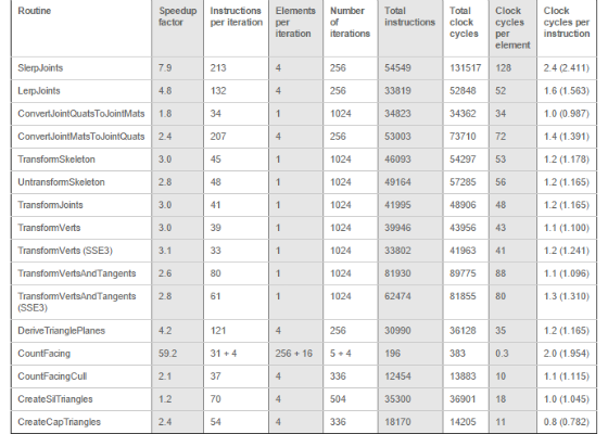
All the presented routines assume the to be processed data is in cache. Optionally prefetch instructions can be added to the routines. However, prefetch distances do not only depend on the CPU type but also the CPU speed, the memory speed, the cache speed, the number of cache levels and several other factors. As such there is no prefetch distance that is optimal on all system configurations. The Intel manuals provide metrics to optimize memory access for a specific configuration with the use of prefetch instructions. The cache usage can generally be improved by pushing models down the pipeline one at a time. As such the results of one step in the pipeline are written to memory through cache and quickly after fetched from the cache during the next step in the pipeline.
Some of the hot cache clock cycle counts presented in the articles are slightly higher when the code is executed on the newer Intel® Pentium® 4 Processor on 90nm Technology compared to the older Intel® Pentium® 4 Processor on 130nm Technology. First of all these hot cache clock cycle differences between these CPUs take nothing away from the performance improvements of the presented optimizations. The Intel® Pentium® 4 Processor on 90nm Technology has a deeper pipeline and slightly higher hot cache clock cycle counts are to be expected. However, the Intel® Pentium® 4 Processor on 90nm Technology scal es to higher frequencies and the increase in frequency made possible by this architecture is higher than the increase in hot cache clock cycle counts due to the longer pipeline. Furthermore the Intel® Pentium® 4 Processor on 90nm Technology has numerous improvements that in many situations actually make it perform better in practice than an Intel® Pentium® 4 Processor on 130nm Technology running at the same frequency. Some of the improvements of the Intel® Pentium® 4 Processor on 90nm Technology architecture over the Intel® Pentium® 4 Processor on 130nm Technology include:
- Larger caches.
- Improved software and hardware prefetch.
- Better static and dynamic branch prediction.
- Increased scheduler queues for improved exploitation of parallelism.
- More instructions are recognized that may break the dependency chain.
- Reduced latency for some instructions like integer multiply and bit-wise logical shifts.
- New instructions like floating point to integer conversion with truncation, instructions for thread synchronization and the Streaming SIMD Extensions 3 (SSE3).
The Intel® Pentium® 4 Processor on 130nm Technology scales from 1.6 GHz up to 3.4 GHz and comes with 512 kB on-die cache. The Intel® Pentium® 4 Processor on 90nm Technology scales from 2.4 GHz up to 3.8 GHz and comes with 1 or 2 MB on-die cache.
The following articles describe the individual routines used in the rendering pipeline and how they are optimized using the Intel Streaming SIMD Extensions.
- Slerping Clock Cycles (PDF 260KB)
- From Quaternion to Matrix and Back (PDF 219KB)
- The Skeleton Assembly Line (PDF 95KB)
- Fast Skinning (PDF 165KB)
- Deriving Triangle Plane Equations (PDF 99KB)
- Shadow Volume Construction (PDF 183KB)
For more such intel resources and tools from Intel on Game, please visit the Intel® Game Developer Zone
Source: https://software.intel.com/en-us/articles/optimizing-the-rendering-pipeline-of-animated-models-using-the-intel-streaming-simd-extensions